برغي كروي مزدوج الصامولة من DFU: برغي كروي غير قياسي مصمم خصيصًا لأدوات آلات CNC
Jun 08, 2026
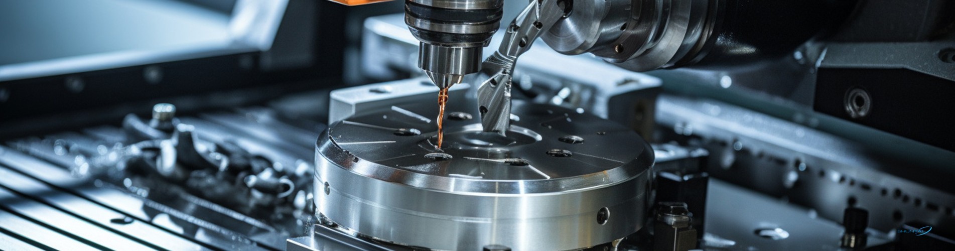
مقدمة عن براغي الكرات الدقيقة لأتمتة العمليات الصناعيةفي عمليات التصنيع باستخدام الحاسب الآلي الحديثة، ومعدات الأتمتة، وأنظمة الحركة الخطية الدقيقة، يُعدّ برغي الكرات المكوّن الأساسي لنقل الحركة، حيث يحوّل الحركة الدورانية إلى حركة خطية سلسة. وبالمقارنة مع براغي الرصاص التقليدية، تعتمد براغي الكرات على كرات فولاذية تدور بين عمود البرغي والصامولة، مما يوفر احتكاكًا منخفضًا للغاية، ودقة عالية في تحديد المواقع، وعمرًا تشغيليًا طويلًا، الأمر الذي يجعلها لا غنى عنها في الآلات الصناعية عالية الأداء.سنتعمق اليوم في موضوعنا برغي كروي مزدوج الصامولة مخصص DFU2005، وهو عبارة عن برغي كروي مخصص غير قياسي مصمم خصيصًا لأدوات آلات CNC، وشرح مزاياه الأساسية ومعايير التصنيع ودعم التخصيص للمشترين الصناعيين العالميين.نظرة عامة على المنتج: برغي كروي مزدوج الصامولة غير قياسي DFU2005يأتي برغي الكرة DFU2005 المميز لدينا بطول إجمالي يبلغ 200 مم (7.87 بوصة)، ومجموعة صامولة مزدوجة كاملة ونهايات عمود غير مكتملة، جاهزة للتشغيل النهائي الثانوي وفقًا لتصميم معداتك.غرضتفاصيلاسم المنتجبرغي كروي دقيق / برغي كروي غير قياسي مصمم حسب الطلبنموذجDFU2005 (يدعم الأحجام غير القياسية المخصصة)ماركةشونتايالمواد الخامفولاذ محامل قياسي GCr15؛ خيارات إضافية: فولاذ مقاوم للصدأ، فولاذ سبيكي، فولاذ كربوني، نحاس، ألومنيومعملية التصنيععمود لولبي ملفوف، عمود لولبي مصقول؛ سير عمل كامل للتصنيع الدقيق باستخدام الحاسوبدرجة الدقةخيارات التفاوت الدقيق C3 / C5 / C7مهلة7 أيام عمل للمنتجات المتوفرة في المخزونميناء الشحنشنغهاي، الصينالحد الأدنى للطلبقطعة واحدة لاختبار العيناتميزة التصميم الرئيسية: هيكل الصامولة المزدوجةيُعد تصميم التحميل المسبق بالصامولة المزدوجة أبرز ما يميز برغي الكرة من سلسلة DFU:1. يزيل الارتداد تمامًا، ويضمن حركة خطية بدون خلوص2. يعزز الصلابة الهيكلية وقدرة تحمل الأحمال لمعدات CNC الثقيلة3. يوفر تشغيلاً فائق السلاسة مع أقل قدر من الاهتزاز أثناء الحركة عالية السرعة 4. يطيل العمر التشغيلي الإجمالي في ظل التشغيل الدوري المستمرلماذا تختار براغي الكرات غير القياسية المصممة خصيصًا لدينا؟1. دعم كامل لتخصيص المعدات الأصليةبصفتنا مصنعًا متخصصًا في تصنيع براغي الكرات الأصلية، فإننا لا نقتصر على توريد النماذج القياسية الجاهزة فحسب، بل نقدم خدمات تخصيص كاملة لتلبية متطلبات معداتكم الفريدة.• طول برغي مخصص، وخطوة لولبية، وقطر خارجي، وشكل لولبي مخصص• تشكيل أطراف الأعمدة حسب الطلب: الطحن، والحفر، والتثقيب، والتجليخ وفقًا لرسوماتك• خيارات متعددة من المواد لتناسب بيئات العمل ذات الأحمال الخفيفة، أو المقاومة للتآكل، أو ذات الأحمال الثقيلة• التغليف والوسم والعلامات التجارية الخاصة المخصصة للموزعين2. التصنيع الدقيق ومراقبة الجودة الصارمةتخضع كل برغي كروي لعملية إنتاج دقيقة متكاملة: الدرفلة على البارد، والطحن باستخدام الحاسوب، والخراطة، والتفريز، والتجويف الدقيق، والتسوية، والتجميع. يغطي نظام مراقبة الجودة لدينا، الذي يشمل فحصًا شاملاً بنسبة 100%، كل مرحلة من مراحل الإنتاج لضمان دقة متسقة. تشمل درجات الدقة المتاحة: أنظمة الأتمتة العامة منخفضة التكلفة (C7)، ومراكز التشغيل متوسطة الدقة (C5)، ومعدات المختبرات/المعدات الطبية فائقة الدقة (C3).3. مزايا الأداء المتميزة• موثوقية عالية ومتانة: يتميز فولاذ محامل GCr15، المعالج حرارياً بشكل احترافي، بمقاومته للتآكل والإجهاد والتشوه حتى في ظل ساعات التشغيل الطويلة.• صلابة عالية بدون رد فعل عكسي: يحافظ هيكل التحميل المسبق ذو الصامولتين على دقة ثابتة تحت الأحمال المحورية الثقيلة.• تشغيل سلس ومنخفض الضوضاء: قناة دوران الكرات المحسّنة تقلل من ضوضاء الاحتكاك، مما يجعلها مناسبة لبيئات ورش العمل الهادئة.• عمر خدمة طويل: يقلل الاحتكاك المنخفض أثناء الدوران من تآكل المكونات، مما يقلل من تكاليف صيانة واستبدال المعدات.4. شحن سريع وطلب مرن• يتم شحن براغي الكرات القياسية من سلسلة DFU المتوفرة في المخزون خلال 7 أيام • الحد الأدنى لكمية الطلب منخفض: تتوفر عينة وحدة واحدة لاختبار جهازك قبل طلبات الشراء بالجملة • تغليف تصدير آمن ومخصص لتجنب التلف أثناء الشحن البحري/الجوي • دعم الشحن العالمي عبر ميناء شنغهاي مع توفير وثائق تصدير احترافيةسيناريوهات الاستخدام الشائعة لبراغي كروية مزدوجة الصامولة من نوع DFUتُستخدم براغي الكرات غير القياسية من سلسلة DFU الخاصة بنا على نطاق واسع في مختلف القطاعات الصناعية العالمية:• ماكينات التفريز CNC، والمخارط، ومراكز التشغيل الآلي • مراحل الحركة الخطية الآلية، أذرع الروبوتات • معدات اختبار دقيقة، آلات أتمتة طبية • آلات التعبئة والتغليف، ومعدات معالجة الإلكترونيات الاستهلاكية • آلات القطع والنقش بالليزراحصل على حلول براغي كروية مصممة خصيصاً لك اليومسواء كنت بحاجة إلى عينة جاهزة من برغي كروي مزدوج الصامولة DFU2005 للاختبار، أو براغي كروية مخصصة غير قياسية تمامًا ذات طول خاص، وتشكيل طرفي ومواد خاصة، فإن فريقنا الهندسي يمكنه تقديم دعم فني احترافي وأسعار تنافسية مباشرة من المصنع.انقر على زر الاستشارة لإرسال رسوماتك، أو متطلبات الأبعاد، أو تفاصيل استخدام المعدات. سنرد عليك خلال 24 ساعة بعروض أسعار ومواصفات فنية مصممة خصيصًا لمشروع الحركة الخطية الخاص بك.
اقرأ أكثر


 شبكة IPv6 مدعومة

 سجل للحصول على اخر اخبارنا